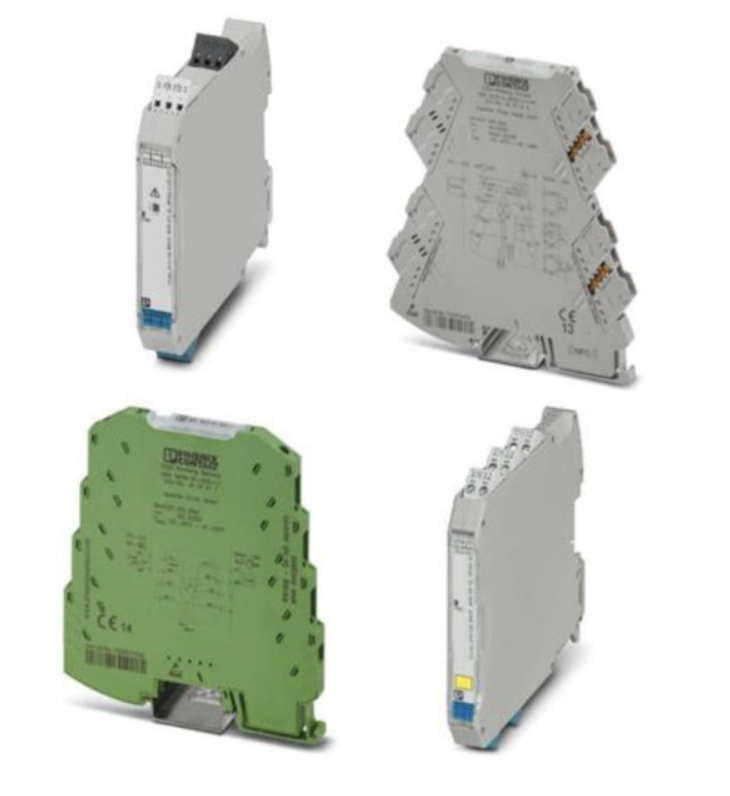
Power Monitors, Transducers & Repeaters

RSP Supply offers a broad selection of power monitors, transducers, and repeaters from trusted manufacturers, including Phoenix Contact and Absolute Process Instruments. These devices play a critical role in industrial automation and control systems by ensuring electrical signals from sensors and measurement devices are accurately converted, conditioned, and transmitted for reliable processing.
Signal conditioners are used to convert, linearize, amplify, filter, and isolate electronic input signals. Many sensors produce signals that are not immediately compatible with control systems such as PLCs, HMIs, or data acquisition equipment. Transducers and signal conditioners adapt these signals into standardized outputs such as 4–20 mA or voltage signals, making them easier to measure, interpret, and control while improving accuracy and system stability.
In complex installations with multiple control circuits, signal isolation becomes essential to prevent interference caused by noise or ground loops. Power monitors and isolation devices provide galvanic separation between input and output circuits using optical or transformer-based isolation methods. This isolation protects sensitive equipment, preserves signal integrity, and ensures consistent data transmission across long distances or between systems operating at different ground potentials.
FAQs
Q: What is the purpose of a signal conditioner?
Signal conditioners convert, amplify, linearize, filter, or isolate input signals from sensors so they can be accurately processed by control and monitoring equipment.
Q: What is a signal transducer?
A transducer converts one type of electrical signal into another standardized signal, allowing compatibility between sensors and measurement or control systems.
Q: Why is signal isolation important in industrial applications?
Signal isolation prevents interference caused by ground loops, electrical noise, or differing ground potentials, which can distort signals and compromise data accuracy.
Q: What is the difference between optical isolation and transformer isolation?
Optical isolation uses light to transmit signals across an air gap, offering high insulation in compact designs but requiring external power. Transformer isolation uses magnetic coupling, works well with AC signals, and typically does not require a separate power source.
Q: Where are power monitors commonly used?
Power monitors are used in industrial control panels, energy management systems, automation equipment, and electrical distribution systems to measure and track electrical parameters.
Why Buy Power Monitors, Transducers & Repeaters from RSP Supply
RSP Supply provides a dependable range of power monitors, transducers, and repeaters designed for industrial control and automation environments. Our selection includes trusted solutions from Phoenix Contact and Absolute Power Instruments that support accurate signal measurement, conditioning, and isolation. Customers rely on RSP Supply for knowledgeable technical support and reliable components that help maintain system performance and data integrity.

