Neutral Grounding Resistors

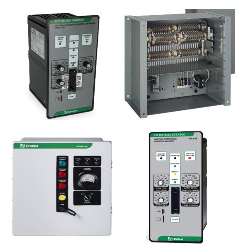
Neutral Grounding Resistors (NGRs) by Littelfuse are essential for improving safety and system reliability in industrial, medium-voltage, and high-voltage power applications. By connecting the neutral point of a transformer or generator to ground through a resistor, NGRs limit ground fault current to a controlled level. This reduces equipment damage, lowers arc flash risk, and protects personnel during ground fault conditions.
To further enhance protection and fault visibility, Littelfuse neutral grounding resistor monitors are commonly used alongside NGRs. These monitors continuously supervise the integrity of the grounding resistor circuit and detect ground faults or open resistor conditions. Many models operate with coil voltage ratings ranging from 28-52 volts to 240 volts, allowing compatibility with a wide range of control circuits and relay schemes used in industrial power systems.
Littelfuse NGR solutions support both low-resistance and high-resistance grounding methods. Low-resistance grounding is often selected where higher fault currents are required for selective coordination, while high-resistance grounding limits fault current to very low levels to minimize damage and maintain system operation. Designed with robust resistor elements and durable enclosures, Littelfuse NGRs and monitors are built to withstand thermal stress and ensure reliable performance under continuous or intermittent fault conditions.
FAQs
Q: What is the purpose of a neutral grounding resistor?
A neutral grounding resistor limits the amount of current that flows during a ground fault, protecting electrical equipment and personnel while allowing protective devices to detect and isolate the fault.
Q: What is the difference between low-resistance and high-resistance grounding?
Low-resistance grounding allows higher fault currents for faster fault detection and coordination, while high-resistance grounding limits fault current to very low levels to reduce equipment damage and maintain system operation during a fault.
Q: Where are neutral grounding resistors typically installed?
They are installed between the neutral point of a transformer or generator and ground in industrial, commercial, and utility power systems.
Q: What materials are used in neutral grounding resistors?
Neutral grounding resistors are typically constructed with resistor elements designed to dissipate heat and are housed in durable enclosures, often stainless steel, to withstand environmental and thermal stress.
Q: How is the resistance value of an NGR selected?
The resistance value is chosen based on system voltage, desired fault current level, and coordination requirements with protective relays and circuit breakers.
Why Buy Neutral Grounding Resistors by Littelfuse from RSP Supply
RSP Supply offers a full range of Littelfuse neutral grounding resistors engineered for dependable ground fault current control in demanding power system applications. Our selection supports both low- and high-resistance grounding strategies and is suitable for industrial, utility, and critical infrastructure environments. Customers rely on RSP Supply for accurate product information, trusted manufacturers like Littelfuse, and knowledgeable support when specifying grounding solutions for safe and reliable electrical systems.

