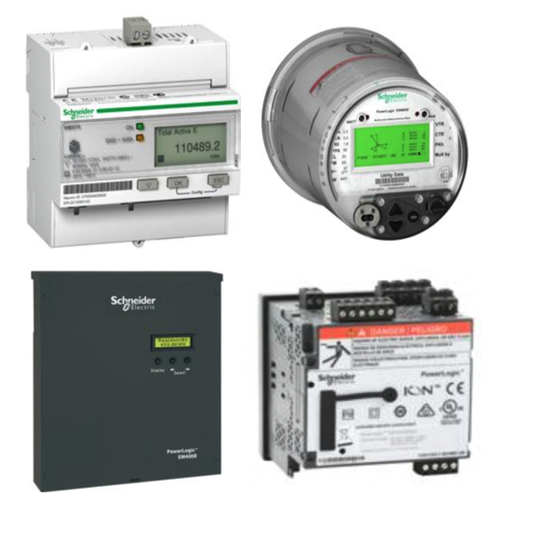
Power & Energy Meters

Energy and power meters are essential tools for monitoring electrical system performance and managing energy consumption in industrial, commercial, and residential environments. These devices provide accurate measurements of voltage, current, power, and total energy usage, giving operators the data needed to evaluate efficiency, track system behavior, and identify opportunities for improvement.
RSP Supply offers a wide range of power meters, energy meters, and enclosed power meters to support various installation and monitoring requirements. Power meters deliver real-time electrical measurements for single-phase and three-phase systems, helping users monitor instantaneous load conditions and system performance. Energy meters record cumulative energy consumption over time, typically displayed in kilowatt-hours (kWh), making them critical for analyzing usage trends, managing operational costs, and improving long-term efficiency. Enclosed power meters combine measurement functionality with protective housings, making them well-suited for panel mounting and harsh or industrial environments.
In addition to meters, a variety of accessories are available to support proper installation and operation. These include current transformers (CTs), mounting hardware, communication modules, and wiring accessories designed to ensure accurate readings and system compatibility. Together, energy meters, power meters, enclosed units, and accessories provide a complete solution for effective electrical monitoring and energy management.
FAQs
Q: What is the difference between a power meter and an energy meter?
A power meter measures real-time electrical parameters such as voltage, current, and instantaneous power, while an energy meter records total energy consumption over time, typically in kilowatt-hours.
Q: Can power and energy meters be used in three-phase systems?
Yes, most power and energy meters are designed for single-phase and three-phase systems, with many models supporting three-phase, four-wire configurations for complex installations.
Q: Why are energy meters important for efficiency monitoring?
Energy meters provide cumulative consumption data that helps identify usage patterns, inefficiencies, and opportunities to reduce energy costs through better system management.
Q: What industries commonly use power and energy meters?
These meters are widely used in industrial manufacturing, commercial facilities, utilities, data centers, and residential applications where electrical monitoring and energy management are required.
Q: Do power meters measure voltage and current directly?
Yes, power meters measure voltage and current directly or through external current transformers (CTs) and voltage inputs, using these values to calculate power and related parameters.
Why Buy Energy & Power Meters from RSP Supply
RSP Supply offers a broad selection of energy and power meters suited for a wide range of electrical monitoring applications. Our lineup includes devices designed for accurate measurement, compatibility with modern electrical systems, and reliable performance in demanding environments. Customers rely on RSP Supply for dependable products, technical expertise, and consistent support when selecting monitoring solutions for energy management and system optimization.s.

