
Starter Overload Relays
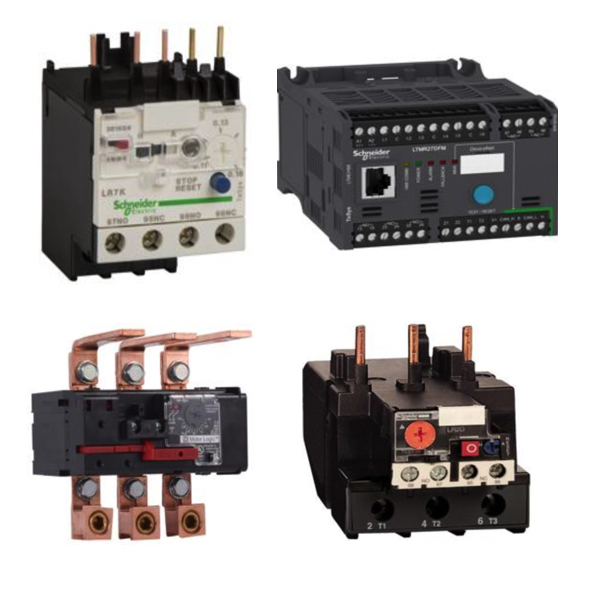
Starter overload relays are a critical component of motor control systems, providing protection against excessive current conditions that can damage motors over time. RSP Supply carries a full line of NEMA and IEC starter overload relays from trusted manufacturers, including ABB, Benshaw, and Schneider Electric. These devices operate alongside contactors and motor starters to ensure safe, reliable motor operation under varying load conditions.
Installed in series with the motor circuit, overload relays continuously monitor the current flowing to the motor. When current exceeds a preset threshold for a sustained period, the relay initiates a protective response, typically opening the control circuit to de-energize the contactor and stop the motor. This protection helps prevent overheating, insulation breakdown, and premature motor failure caused by overload or locked-rotor conditions.
Modern overload relay designs include both traditional IEC thermal overload relays and advanced electronic overload relays. Electronic models offer expanded protection capabilities such as phase loss detection, adjustable trip settings, diagnostics, and communication options for integration into control and monitoring systems. Whether used in simple motor starters or advanced automation environments.
FAQs
Q: What is the purpose of a starter overload relay?
A starter overload relay protects motors from prolonged overcurrent conditions by interrupting power when current exceeds safe operating limits.
Q: What is the difference between IEC and electronic overload relays?
IEC thermal overload relays provide protection based on current-related heating, while electronic overload relays can detect additional conditions such as phase loss and provide more precise protection and diagnostics.
Q: How are overload relays installed in a motor control system?
Overload relays are typically installed in series with the motor circuit and are often mounted directly to the contactor or within the control panel.
Q: What role do heater elements and ratchet wheels play in overload relays?
Heater elements generate heat proportional to motor current, which moves a ratchet wheel or trip mechanism to activate the relay when unsafe current levels are reached.
Q: Do three-phase overload relays offer communication capabilities?
Yes, many three-phase overload relays support communication protocols such as Modbus, Profibus, or Ethernet/IP for real-time monitoring and fault reporting.
Why Buy Starter Overload Relays from RSP Supply
RSP Supply offers a comprehensive selection of NEMA and IEC starter overload relays designed to protect motors in industrial control systems. With products from ABB, Benshaw, and Schneider Electric, customers can select solutions that match their performance, protection, and integration requirements. RSP Supply is trusted for technical expertise, reliable industrial components, and solutions built for long-term motor protection.