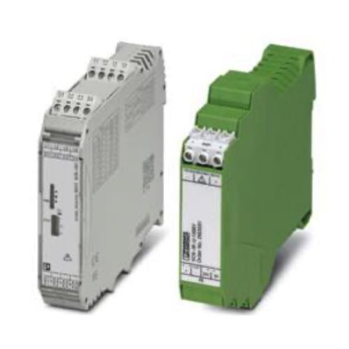
Voltage Transmitters & Transducers

Voltage transmitters and transducers are critical parts of electrical systems, performing two key functions. First, they measure the voltage across various applications. Second, they make the voltage levels easier to interpret and manage, sending out standard analog or digital signals that are more convenient to work with. These devices are used in what's called "power quality" applications—places where the consistent and accurate measurement of voltage is absolutely vital for safety and operational efficiency. They monitor the performance of power distribution systems and electric motors, and they figure prominently in "energy management" applications where the aim is to keep both electrical systems and the businesses that run them safe and profitable.
In long-distance data transmission or within intricate systems, the input voltage and proportional output of a voltage transmitter are usually well isolated. This good isolation renders the transmitter safe to use and minimizes the chances of data being misinterpreted in a way that could cause any operational problems. Transducers, like transmitters, incorporate good isolation, but they do more than just protect sensitive components from interfering voltages. They condition the signals to make the output of the system much more reliable. Voltage transducers, therefore, help not only in accurately measuring the system variables but also protect the downstream equipment from those same high-voltage signals.
How to Use a Multimeter
Measuring AC Voltage
Set the dial to the AC voltage symbol and plug the red probe into the voltage port. Place the red probe into the hot terminal block and the black probe into the neutral terminal block. Make sure the probes are fully seated to something that can conduct electricity, like the screws on the terminal blocks. The measurement is taken in parallel with the load.
Measuring DC Voltage
Set the dial to the DC voltage symbol and leave the probe in the same port as it was for the AC voltage measurement. Place the red probe to DC positive and the black probe to DC negative. The measurement is taken in parallel with the load.
Measuring Current or Amperage
Set the dial to either milliamps or amps. Move the red probe to the DC amp port. The multimeter is now set to measure DC current. Remove the wire that is sending power to the load and place one probe on one end and the other probe on the other, to complete the circuit, allowing power to bypass the load. The meter will break the circuit and measure the current in series with the voltage source. This allows the meter to measure the current that is going to the load.
Measuring resistance
Make sure that the load is disconnected from the electrical circuit, otherwise, the resistance measurement will not be accurate. Set the dial to the ohm symbol and place the red probe into the voltage port. Place one probe on one conductor and the other probe on the other. Take the reading.
Measuring Continuity
Meter settings stay the same as previous measurements, with the addition of pressing the audible button. Place the probes anywhere on the electrical circuit. An audible tone will sound if there is a continuous, point to point connection. If there is no sound, there is break in the electrical connection, possibly caused by broken or frayed wires.

