Transcript:
[0m:4s] Hi I'm Josh Bloom, welcome to another video in the RSP Supply education series. Today we're going to be talking about multimeters. More specifically, how to use multimeters.
[0m:13s] Multimeters are tools that are used to measure voltage, current, and resistance, that can be very helpful in measuring any type of electrical equipment that we might be troubleshooting or working on.
[0m:25s] Again, today we're going to be talking about how to measure current, voltage, and resistance with the multimeter. In order to do that I've created a very simple circuit and let me explain how this works. We have 120 volts coming in from a common outlet that you might find on your wall. That 120 volts comes over to this set of terminal blocks and is then transferred to a power supply. Again, a power supply is a device that converts power from one type to another. In this case it's taking 120 volts AC power and converting that to 12 volts, DC power. We then have 12 volts coming out to this terminal block and these terminal blocks and ultimately powering our load, which is a 12 Volt fan.
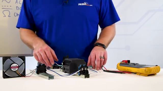
[1m:4s] So, the first type of measurement that we're going to talk about is how to measure AC voltage. Now, when measuring AC or DC voltage, we want to make sure that we measure voltage in parallel with our load. I've written on the board here. A little diagram to help illustrate that just a bit better. You can see here, we have our voltage source depending on if it's AC or DC, it's either negative or neutral,
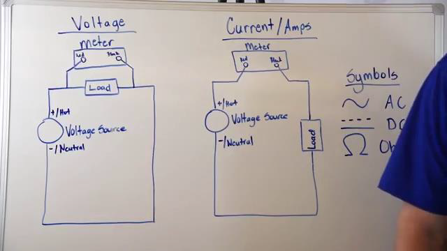
[1m:29s] and then our load.
[1m:31s] We have our meter measuring on one side of our load and on the other side of our load again in parallel, this allows us to measure voltage.
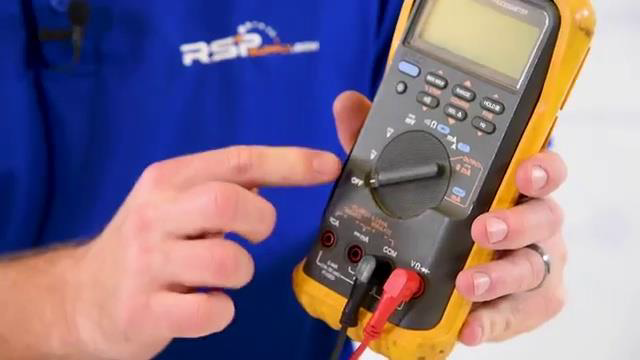
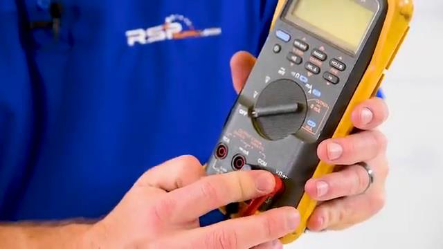
[1m:39s] So, now I'm going to actually show you how to measure voltage on the meter itself. Keep in mind, not all meters are the same, however, all meters do have two probes that give us the ability to measure voltage, or resistance, or amperage, again, depending on the meter that you have. The first thing we want to look at when we're ready to measure voltage is to ensure that our mirror is set to the proper settings. We first are going to turn our meter to AC voltage symbol.
[2m:7s] I have illustrated that here on the whiteboard. The AC voltage symbol.
[2m:11s] We then want to make sure that our probes are plugged into the proper spot. In this case, our black probe goes into the calm,
[2m:18s] and our red probe goes into the voltage
[2m:22s] port.
[2m:23s] At this point, we are now ready to measure AC voltage. Let me show you how we make that measurement. We now need to take the probes in this case our red probe will go to our hot terminal block, and the black probe to our neutral terminal block. We want to make sure those probes are fully seated to something that can conduct electricity in this case, the screws on the terminal blocks themselves.
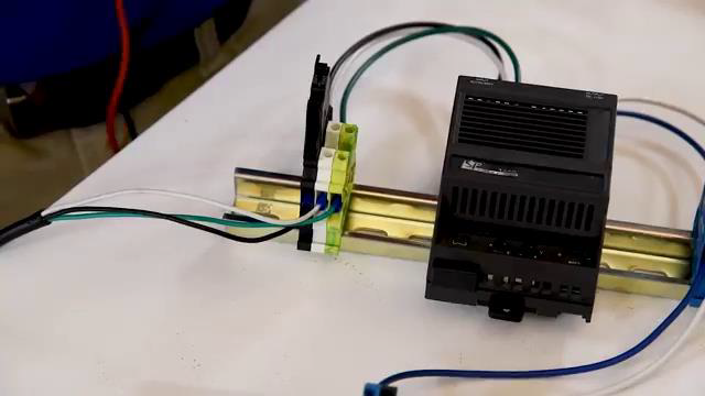
[2m:45s] I can now read on the Volt meter that I have 120 volts of AC power.
[2m:50s] Next we're going to talk about how to measure DC voltage. Just like with AC voltage, as you can see on our diagram, we are going to measure in parallel with our load. We do, however, have to make a few changes on the meter in order to measure DC voltage.
[3m:6s] The only change we actually have to make is to change our voltage from AC to DC. We can leave our probes in the same spot as they are set to measure voltage. We can then take our probes
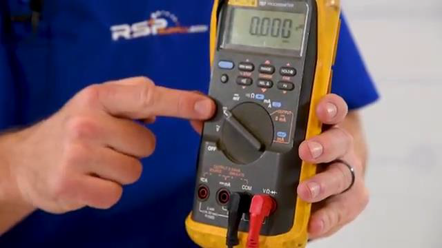
[3m:19s] and measure DC voltage. In this case, our red probe to DC positive
[3m:25s] and our black probe to DC negative.
[3m:28s] And looking at my meter, I can see that we are getting 12 volts of DC power.
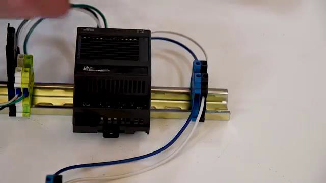
[3m:34s] Now we're going to talk about how to measure current or amperage in an electrical circuit with our multimeter.
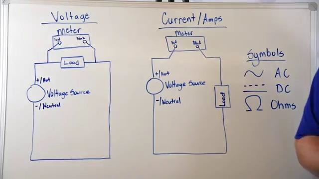
[3m:41s] Different from voltage, when measuring current, we need to measure the current in series with our electrical circuit. You can see up on the whiteboard here. How I've demonstrated that we have our voltage source with either DC negative or neutral, and then our load, and then we have our meter actually breaking that circuit and measuring the current in series with our voltage source. This allows us to actually measure the current that is going to our load itself. Now, keep in mind, not all meters can measure current, and some meters can only measure current in either AC or DC voltage. So, you need to check your multimeter to see what is capable of.
[4m:20s] Now, let me demonstrate how we actually measure current using our multimeter. Keep in mind that we do have to make some changes to the multimeter in order to measure current. :et me show you how we do that.
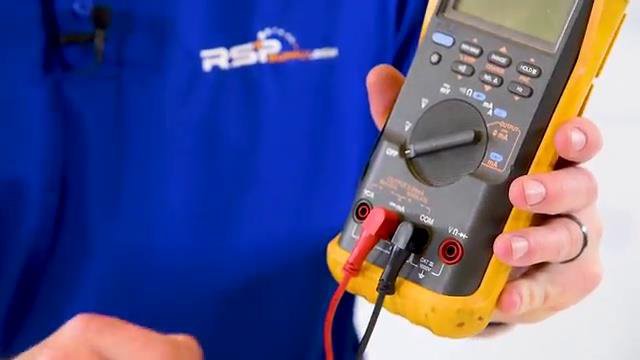
[4m:29s] First, we're gonna move our dial from voltage to measure either milliamps or amps. Then we need to move our red probe in this case to the DC AMP reading setting. Now my multimeter is set to measure DC current.
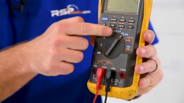
[4m:46s] Now, let me actually show you how to make the measurement. In this case I'm gonna remove the wire that is sending power to our load. I am then gonna, take my probes
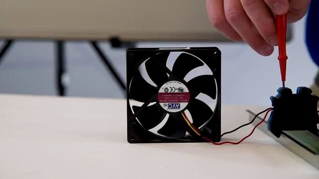
[4m:56s] and put it on one end, and the other end to again complete that circuit allowing power to pass to my load. In this case, our fan. I can now measure current and I see that we have 0.3 amps that are being drawn by our fan. Now, let me show you how we measure resistance in an electrical circuit. It is important that when we measure resistance in our circuit, or more specifically in a load, that we make sure that load is disconnected from our electrical circuit. If it is connected, we will not get an accurate resistance measurement.
[5m:28s] Again, like the other types of measurements, we need to make sure that our meter is set to the proper settings.
[5m:34s] Let me show you what those settings look like.
[5m:36s] First, we're gonna take our dial and set it to the ohm symbol. Then, in this case, our black probe goes into the calm,
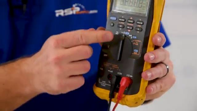
[5m:46s] and our red probe goes into the voltage
[5m:49s] port.
[5m:50s] First, we're going to disconnect the fan from our electrical circuit. At this point, we have the ability to measure resistance. I'm going to take one probe and put it on one conductor of my fan and I'm going to take the other probe and place it on the other conductor. I can then read my meter and see that I have 36 miliohms of resistance in this fan.
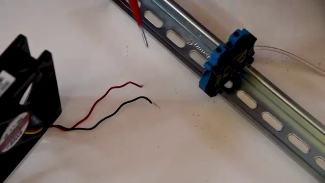
[6m:11s] Now let's talk about how to measure continuity. Continuity is a very common and helpful way to measure electrical circuits. It allows us to measure from point A to point B to make sure that we have an electrical connection or that we don't have any break in our electrical connection. If the wires have broken or frayed and are not touching each other anymore, we will not have continuity.
[6m:32s] We can also use the continuity measurement with an audible tone. Most multimeters give us the audible tone feature so that when we are checking our point to point connection, or continuity, we can simply listen for the tone. Once we hear the tone we know we have a good electrical connection with no breaks. Now, let me show you how we check continuity. Our meter settings stay exactly the same. The only thing we need to do in this case is press the audible button to give us a tone when we are checking point to point or continuity.
[7m:2s] I then take a probe and simply place it anywhere on my circuit.
[7m:6s] From point, A to point B to make sure I have an electrical connection. I then hear an audible tone.
[7m:12s] If I check a point to point and I don't hear an audible tone,
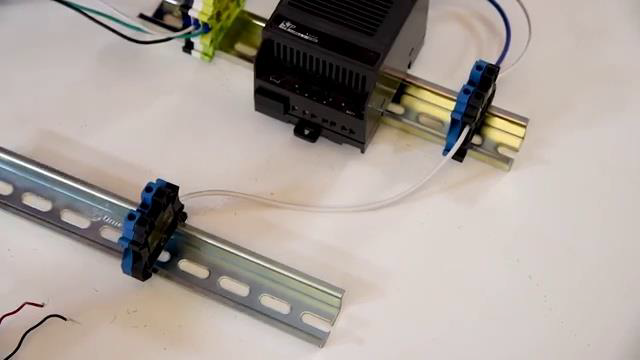
[7m:16s] I know that I don't have that connection made.
[7m:20s] When you hear the tone, you have a connection. For a full line of industrial electrical equipment and thousands of other products, please go to our website. For more information or other educational videos, go to RSPSupply.com, the Internet's top source for industrial hardware. Also, don't forget: like and subscribe.


