
Understanding_Wiring_Diagrams_Part_4.pdf
Transcript:
[0m:4s] Hi I'm Josh Bloom, welcome to another video in the RSPSupply education series. If you find that these videos are helpful to you, it certainly helps us out if you could give us a big thumbs up and subscribe to our channel. In today's video, we are continuing on in our brief series in which we are learning how to understand wiring diagrams specifically related to control, so that you might be able to read and or design your own electrical control system. In our last video, we talked about how to read and understand the main power distribution portion of the electrical diagram. We looked at the various components that are commonly used in power distribution and how those components are represented on a drawing. We also looked at how power on a diagram transitions from one type of power to another, for instance from AC power to DC power, and also how voltage changes are represented, as well as any circuit breakers, fuses, and other common power distribution components that are represented. For the purpose of this video, we want to start talking about the signal portion or control portion of the diagram and how to read, interpret, and draw these types of circuits. Signal wiring uses many of the same principles as power distribution in regards to how they function, and therefore, in many cases are drawn in the same way on an electrical diagram. Keep in mind the items we discuss today are meant to be a guide but are not intended to replace proper electrical design education. It is important to consult with an electrical engineer or qualified person to ensure the system you design meets all electrical codes and will function safely and as expected. With that said, let's look at a few different signal loops and how they are drawn on one of these diagrams. Now, as mentioned before, many of the same principles that we learned in the power distribution diagram video are going to apply when we're trying to understand signal diagrams and IO diagrams. While IO and signal diagrams can be more complex, especially when we're talking about things like analog signals because there's so many different variations on how we wire that, many of the same principles apply. So try to keep that in mind when we're looking at the different examples we're going to see today. Just understand that if we understand the path of the flow of where that power is going, we're going to better understand how these different diagrams work. So, let's go ahead and look at our first example. Now, here you see, we have an example of an analog input
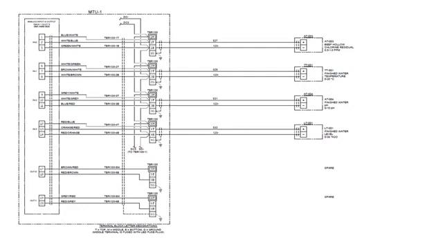
[2m:58s] card on a PLC and we have, in this case, four different signals that are coming into this particular PLC. On the left here with this long, tall, rectangular square it's representing an analog input card on a particular PLC. You can see here the IN1, IN2, IN3, each of those three terminals represent one input signal. Now, again, with analog signals they're a bit more complex in how they're wired. Don't get too distracted by looking at this current diagram thinking it's very complex. What you want to understand are the basics right now. You want to understand that this IN0 represents one analog input. If we come out to the very right you're going to see some instrumentation. This is instrumentation that's going to be in the field, meaning it's not in our control panel. It may be located far away.
[3m:56s] And in this case, we have four different instruments. We have a chlorine residual instrument that's gonna send a value back to the PLC. We have water temperature, finish water pH, and water level. Each of these instruments is going to send a signal back to the PLC. Now again, an analog signal is a ranged signal, meaning it's going to be giving us a varying value. It's not like a digital signal that’s just on or off.
[4m:24s] Analog is a range so it could be anywhere between one and 100. This is typically represented as a 4 to 20 milliamp signal and then that is scaled to meet your specific range. It doesn't have to be 4 to 20 milliamps, it could be a different type of signal, but that's one of the most common. So in this case, you can see this bottom one here. We have water level that's going to be sending somewhere between a 4 and a 20 milliamp signal back to our PLC on one of these wires. One of these wires here is going to be a signal wire, the other one's going to be tied to ground. You can see this bottom one looks like it's our ground wire, and this top one is going to be the actual signal wire. Okay, so that's essentially what's happening in this diagram. In the middle here you'll see some terminal blocks. These are used just as an interface between our instrument in the field and the PLC, so we're not wiring directly from the instrument to the PLC, we're wiring to these terminal blocks. In this case, these are multilevel terminal blocks. So that's essentially what's happening here. I know that there's a lot to look at, and it looks very complex when you look at it, but it's simply just some simple signals coming back to an analog input card on a PLC. Now let's look at our next example.
[5m:46s] Here it's a little more simplistic. These are digital inputs. Again, these long tall rectangles represent a digital input card on a PLC.
[5m:58s] Now what's important to note here is we want to look at the flow of
[6m:4s] energy. Where's the power going? For example, let's look at
[6m:10s] DC4 up here. That's power that's coming into the circuit. That's running into this terminal block
[6m:16s] that goes out to the field that says
[6m:20s] plant entry intrusions. This is going to be maybe like a door or something like that. This little symbol means it's normally closed.
[6m:27s] So if that door opens,
[6m:29s] the PLC is notified that “Hey I've lost voltage.” Because right now you've got
[6m:34s] power running through, this is normally closed. So normally the PLC sees this power.
[6m:39s] If that door is opened,
[6m:41s] this contact opens, and the PLC loses that power.
[6m:44s] And then the operator can be notified. Okay, so in this case let's go down and look at a different signal. You have this power that's jumpered to all these terminals.
[6m:55s] So down here we have on this signal 10.
[6m:59s] We have power running through this terminal block
[7m:2s] out to a pump.
[7m:4s] Pump one running, this is a run status for a pump. This is normally open.
[7m:9s] When that pump turns on, it starts to run, this contact will close, then sending
[7m:15s] power to the PLC. And that power detects that voltage. As soon as it detects that power,
[7m:21s] it will notify the operator that “Hey, that pump is now on.”
[7m:25s] Very, very simplistic. So again, we're just looking at the flow of power.
[7m:29s] Power goes out to the device, it's usually just some sort of a dry contact meaning it's just an open or close, that's all it's looking for. And then that power goes back to the PLC and then indicates what’s going on.
[7m:43s] Very simple. Let's go ahead and look at our next example.
[7m:45s] Here we're not looking at a digital input or an analog input, we're looking at something a little bit different. These are thermocouples. So again, this is a different type of signal or input or output. Here you see, we have power that's being supplied to a PLC card.
[8m:6s] In this case, these cards require power in order to do the monitoring that they need to.
[8m:12s] And then you can see there's several sets of terminals for one signal.
[8m:17s] So, depending on the manufacturer of the PLC or the card that you're using, you need to wire to different terminals. In this case you've got four different terminals you can wire to depending on the specific application.
[8m:30s] So, don't worry too much about what terminals go where, that's going to depend on what hardware you're using. But in this case, you can see that
[8m:38s] each of these groups of terminals are wired to an individual thermocouple. And then that thermocouple is read to the card, which is then interpreted by the PLC and then it's going to be displayed on an HMI screen or wherever you might find that information.
[8m:57s] What's important to note here is that when you're looking at signals and IO, in many ways it functions the same way as power.
[9m:6s] We're looking for power in and power out.
[9m:9s] We're looking for a path. It has to have a starting and an ending. And if you don't have that path, it's not going to function properly. If you can understand that, you're going to have a much better time understanding these more complex IO and signaling
[9m:28s] drawings and be able to do those yourself
[9m:32s] when the time comes.
[9m:33s] As you can see, drawing various different signal loops is not that difficult if basic electrical principles are followed and understood. However, care should always be taken to ensure that any circuits that are being drawn are done so that they meet all local codes and guidelines. Safety should always be a top priority when creating any electrical design schematic. Once the safety of a circuit has been addressed, proper function will follow. For a full line of industrial control panel hardware and thousands of other products, please go to our website. For more information or other educational videos, go to RSPSupply.com, the Internet's top source for industrial hardware. Also, don't forget: like and subscribe.