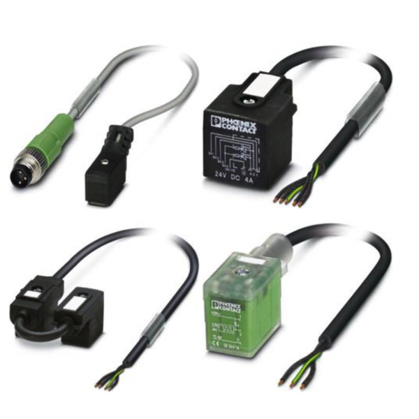
Valve Sensor-Actuator Cable Assemblies

Valve sensor cable assemblies are specialized cable assemblies designed to connect valves and valve connectors in various industrial environments. These assemblies are often made with sensor actuator cable, a type of cable that is designed to be both flexible and durable. The connector type used in these assemblies usually complements the needs of industrial applications, providing secure and reliable connections.
In an industrial environment where ruggedness and reliability are crucial, these cable assemblies often feature shielding and may be made of materials suitable for harsh conditions such as exposure to high temperature, dust, and other environmental factors. For example, PVC is often used for its durability and resilience.
Phoenix Contact is one of the manufacturers that offer a range of these specialized sensor actuator cable assemblies, featuring various numbers of positions such as 3-position, 4-position, and 5-position connectors. The range of available positions offers flexibility in installation and application, catering to the diverse needs of industrial settings.
More Information about Valve Sensor Cable Assemblies
The cable length can vary and should be selected based on the specific requirements of the application. Whether you are dealing with high-speed communication between devices or need high flexibility for installation in tight spaces, choosing the correct cable length is essential.
In terms of color coding, options like red and yellow may be offered to make the installation process easier and to help avoid mistakes that could affect the reliability of the connected systems.
Valve sensor cable assemblies are an integral part of many industrial applications. They offer benefits like secure connections, durability, and flexibility, making them suitable for a range of uses from basic valve control to more complex automated processes. These assemblies are tailored to meet the challenges of industrial environments, providing a combination of features that ensure both longevity and optimum performance.
Analog vs Digital Control Signals: The Basics
Digital Signals
Digital signals are represented in either a true or false. There is no gray area with digital signals. An example of this might be a light switch. A light switch is either on or off. Another example of this might be a motor that is running or not running. Digital signals can be generated with both AC and DC circuits with varying voltages, currents and resistance. Some practical examples of using digital signals in an industrial environment might be if a pump is running or not running or a whether a valve is open or closed.
Analog Signals
Analog signals convey information in the form of a range. A light switch might be on or off as a digital signal, but a dimmer switch would be an analog signal. It can be on or off, but it can also be somewhere in between. A practical example of using analog signals in an industrial environment would be if there is a need to measure the level of a tank; whether it's full, empty or somewhere in between. Analog signals can take many different forms with some of the more common being a 4 to 20 milliamp signal or a 0 to 5 or 0 to 10 volt signal.
Communication
Communication in a device can either be sent or received. Whether that data is sent or received depends on the type of information. Is there a need to monitor the status of something? If so, an input needs to be received about that information. Is there a need to control something? If so, an output needs to be sent about what needs to occur. Receiving inputs and setting outputs are both things that can be accomplished by using both digital and analog signal types. Therefore, the signals are referred to as analog outputs (AO), analog inputs (AI), digital inputs (DI) or digital outputs (DO).

