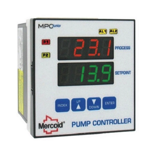
Pump Controllers

Pump controllers are essential for controlling, monitoring, and protecting pumps in water and fluid management systems across industrial and commercial environments. These devices receive signals from level transmitters, leak detection sensors, pressure switches, or other process instruments and regulate pump operation to maintain stable system conditions. Typical applications include wastewater treatment facilities, pump stations, irrigation systems, and industrial process equipment.
RSP Supply carries pump control solutions from trusted manufacturers such as Dwyer Instruments, including single-channel and dual-channel leak detection relays designed to monitor conductive liquid leaks and trigger alarms, shutdowns, or pump actions when leaks are detected. For more complex pumping systems, quadraplex pump controllers provide coordinated control of multiple pumps, allowing for lead/lag operation, load balancing, redundancy, and improved system reliability in high-demand applications.
Pump controllers also help manage electrical power delivery to pumps, supporting automatic start/stop functions, pump sequencing, and protection against dry running, overpressure, overloads, and electrical faults. Built for demanding environments, many controllers feature rugged enclosures, diagnostic indicators, and fault monitoring to support long-term, reliable operation in harsh industrial and commercial settings.
FAQs
Q: What is a pump controller used for?
A pump controller manages the operation of a pump by receiving input signals from sensors or transmitters and controlling when and how the pump runs to maintain desired system conditions.
Q: What types of signals do pump controllers use?
Pump controllers typically use signals from level transmitters, pressure sensors, flow sensors, or float switches to determine pump operation.
Q: Can pump controllers help protect pumps from damage?
Yes, many pump controllers include protection features such as dry-run detection, overpressure protection, overload monitoring, and fault alarms to help prevent equipment damage.
Q: Are pump controllers used only in industrial applications?
No, pump controllers are used in a wide range of applications, including small commercial systems, municipal water systems, irrigation setups, and large industrial processes.
Q: How does a pump controller work in level control applications?
In level control applications, a pump controller can start the pump when the liquid level drops below a set point and stop it when the level reaches a defined upper limit, using input from level sensors or transmitters.
Why Buy Pump Controllers from RSP Supply
RSP Supply offers a comprehensive selection of pump controllers designed for reliable water and fluid management across industrial and commercial applications. These controllers provide accurate control, built-in protection, and durable construction suited for demanding environments. Customers rely on RSP Supply for quality components, technical expertise, and dependable solutions that support efficient and reliable pumping system operation.

