Industrial_Control_Panels_in_depth_look_Part_2_IO.pdf
Control Panels, IO: Inputs and Outputs
What is IO?
- IO stands for "Inputs" and "Outputs" It is the wires coming to and from the panel
- This IO is connected to instruments and sensors wired in the "field"
- IO can consist on many different signal types including: Analog, Digital, RTD, Etc.
- The IO portion of the panel acts as the interface between the PLC and the field instrments
Proper Wiring Techniques: IO
- Make sure to use the correct wire for the signal you are wiring
- Analog signals have a grounding shield wire that must be landing in the panel
- It is a good practice to use fuse blocks to protect the PLC from any surges that may occur in the field
- It is common to use relays to act as a barrier to assist in protecting the PLC for Output Signals
Transcript:
[0m:4s] Hi I'm Josh Bloom, welcome to another video in the RSP Supply education series. In today's video, we are going to be taking another look at industrial control panels. More specifically, we are going to be looking at the IO portion of the panel. For more information about industrial control panel basics, please see our other video which we will link in the description below. In almost all industrial control panels, there is a portion that is designated for IO.
[0m:31s] IO stands for inputs and outputs. This is where the wires will actually be terminated into the panel from devices and instruments that are being monitored and controlled by the industrial control panel itself.
[0m:46s] Remember the purpose of an industrial control panel is to monitor and control the various instruments and devices that it is wired to in the field. This monitoring and control would not be possible without the IO portion of the panel that the devices are actually connected to. Today we're going to be talking in depth about the different types of IO that can be wired into a panel.
[1m:10s] We will discuss how to actually wire the IO. We will also show you some steps that are critical to ensure that devices being wired into the panel are sending and receiving the data that is intended.
[1m:23s] Let's first discuss the different signal types that make up the IO in a panel.
[1m:28s] We will first talk about digital signals. Digital signals are designed to measure and control a value that is either on or off. It's easy to think of this like a common light switch in our home, we can turn it on or off, but we do not have the ability to control how much light we get or how bright or dark the light is. This again is how digital signals work on or off, true or fault, or 1 or 0.
[1m:54s] An industrial example of this would be monitoring the state of a motor, for instance.
[1m:59s] It is either running or it is not running. We only have two choices on or off.
[2m:5s] Now let's talk about analog signals.
[2m:8s] Analog signals are intended to measure and control a range of values to better illustrate this point. Think of that same light switch. Instead of just turning it on or off, let's assume we're using a dimmer switch. The dimmer switch gives us the ability to turn the light on and off, but it also gives us the ability to manipulate the light output anywhere in between the fully on or fully off state of that switch. This, again, is how analog signals work.
[2m:37s] We measure and control a range of values.
[2m:40s] An industrial example of this would be measuring the level in a tank, for instance, or measuring the amount of flow or pressure within a pipe. Now that we have talked about both digital and analog signals let's discuss how we can use those signals. In these control signals, we have the ability to either send out data or receive data back to our panel.
[3m:3s] This data, input and output, ultimately, is what gives us the ability to monitor and control the intended environment.
[3m:11s] When we send data out, this is referred to as an output signal.
[3m:15s] You can use both analog and digital signals when sending an output signal. For example, a digital output could be a run command to a motor.
[3m:25s] So, in this case, you would send a signal that tells a motor to either start or stop.
[3m:29s] And analog output could be used to actually control the speed of that same motor since analog signals gives you the ability to control a range of values. These are again, examples of output signals.
[3m:42s] Now let's talk about input signals.
[3m:45s] Inputs are when we receive data from either a digital or analog source.
[3m:50s] This data is captured and interpreted by the PLC, or the programmable logic controller, within our cabinet. Just like with output signals, inputs can be either digital,
[4m:2s] which might be telling you if a motor is running or if a door has been open or closed, or analog, which would be able to tell you if the pressure in a pipe is too high or if the level in a water tank is too high or too low.
[4m:15s] All of these are examples of input signals.
[4m:19s] There are other signal types that we have not discussed such as an RTD or thermal couple that can make up the IO with an industrial control panel as well. Now that we've talked about the most common signals you will find in a panel, let me show you in this panel we have here where each type of signal an IO point are
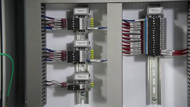
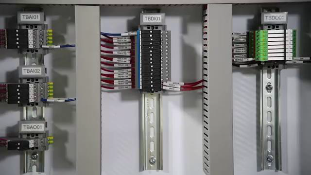
[4m:38s] and how to wire them and make sure we can send and receive data properly. First, let's talk about analog input signals, which you can see right here.

[4m:49s] In an analog input, we commonly use a type of wire that has a shield on the wire. This Shield protects the signal from noise or disturbances that might interfere and not give us the desired result on that input.
[5m:5s] It also has a ground wire. This is critical when wiring analog input signals. On this particular terminal block, we have a place to land that ground wire.
[5m:18s] This is where any disturbances are fed to and distributed in the signal so that we don't see that in the actual input to our PLC. It is important to note that the ground on our twisted shielded pair wire

[5m:32s] be terminated in the panel and not at the instrument itself. Depending on how the instrument is powered will dictate how we wire that instrument and ultimately how we wire the panel. In this case, we are providing power to the instrument.
[5m:46s] So, we would send power out on one wire to the instrument,
[5m:51s] and on the wire coming back, is referred to as our signal wire. This is actually what has the data that gets sent to our PLC. Again, it is very important to make sure that we land the ground wire in the panel itself.
[6m:4s] Now, let's talk about analog outputs. These are going to be wired much in the same way as an analog input. However, we don't have any need to provide power in most cases for analog outputs. However, we do still use a shielded wire, in this case, a twisted shielded pair. We still also want to make sure that we land that ground portion of that shielded wire in our panel to protect that output signal. Again, we're going to be sending an output signal that will control a range of values such as a motor speed or possibly a valve position. Now let's talk about digital inputs which you can see right here. In most cases on a digital input, we wire those with a relatively low voltage. We send that voltage out to whatever device that will be switching

[6m:56s] that power. When that power is closed at the device, it will send that power back to our panel on our signal wire which you can see here.
[7m:5s] That signal wire is wired to our PLC. All that PLC is going to be looking for is if it sees voltage. If it sees voltage, it is either on or off, or in this case, true or false, and that is how we determine the status of a digital input signal.
[7m:22s] In this case, there is no need to use any kind of special wire that we use with our analog signals. We can simply use a regular MTW or THHN wire to send and receive those signals.
[7m:35s] Now let's talk about digital output signals, which you can see here.
[7m:39s] When we use a digital output signal, we typically use those in conjunction with a set of relays. The reason we use these relays is it allows us to send a very low voltage to the relay coil.
[7m:52s] When that coil is energized, it switches the contacts on the contact side of the relay, allowing us to send a much higher voltage to power any kind of output device. Much like with our digital input signals there's no need to use any special wire or a twisted shielded wire like we would with our analog signals. With a digital signal, we can simply use MTW or THHN, both on inputs and outputs. Keep in mind when we're talking about the IO portion of an industrial control panel, we want to make sure we know where all that IO is going to be coming into our panel. Typically, this is going to be located at the bottom of the panel.
[8m:34s] By doing this, we can make sure that we are properly organizing and wiring your IO.
[8m:40s] By doing this, you will be able to successfully monitor and control all the devices and instruments in the field with very little issue.
[8m:48s] For a full line of industrial control panel components and thousands of other products, please go to our website. For more information or other educational videos, go to RSPSupply.com, the Internet's top source for industrial hardware. Also, don't forget: like and subscribe.


