
Transcript:
[0m:4s] Hi I'm Josh Bloom, welcome to another video in the RSPSupply education series. If you find that these videos are helpful to you, it certainly helps us out if you could give us a big thumbs up and subscribe to our channel. In today's video, we want to talk about situations where the control signals we generate or receive are being distorted due to various factors that can be found along the signal path.
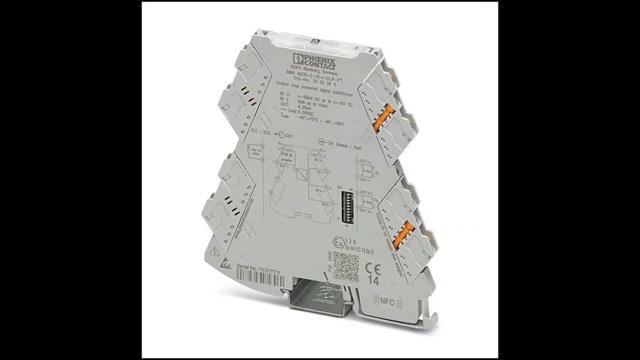
[0m:28s] More specifically, we want to discuss a method that is commonly used to eliminate these distortion issues. The method that I am referring to is to use a signal isolator or an integrated signal isolated PLC module.
[0m:42s] When dealing with scenarios that involve many different control circuits and input and output signals, it is not uncommon to encounter scenarios that will present signal distortion issues. This distortion can corrupt the input or output signal, rendering the data virtually useless. We hope that by the end of this video, you better understand some of the reasons that cause these types of problems. We also hope to explain the basics of signal isolation and how it works.
[1m:13s] Please keep in mind that this video is intended to cover only basic principles of this topic and is not intended to replace proper electrical instruction.
[1m:23s] If you encounter a scenario in which you find signal isolation might be needed, please consult with a qualified person to ensure you are following all proper electrical codes and guidelines. With that said, let's look at some situations where you might encounter signal distortion, and how signal isolation can help correct that issue. Let's look at a scenario where you have a transmitter that is sending a 4–20 milliamp signal to a PLC.
[1m:53s] In this scenario, let's assume the transmitter is located several hundred feet away in a different building.
[1m:59s] In this scenario, both the transmitter signal connection is grounded, per proper instruction, as well as the signal connection at the PLC.
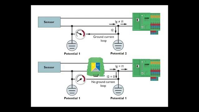
[2m:8s] Because we have grounded this signal, both at the transmitter and PLC, we have the possibility of different ground potentials.
[2m:18s] This difference in potential can cause current to flow between the two points.
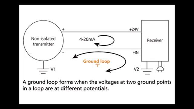
[2m:23s] This flow of current has the chance of distorting the control signal that is being sent to the PLC.
[2m:29s] This current flow between two different ground potentials is referred to as a ground loop. Ground loops can be fairly common in industrial control applications, and because of the issues that they cause, they need to be controlled. This is where signal isolation comes into play.
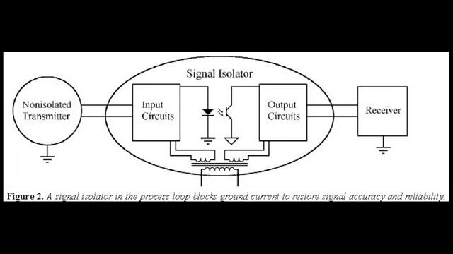
[2m:59s] Signal isolation provides an electrical isolation between input and output circuits.
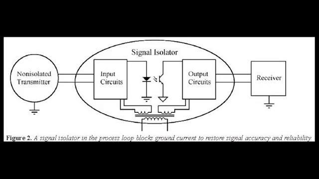
[3m:6s] This is sometimes also referred to as galvanic isolation.
[3m:10s] This physical break in the galvanic path of the control signal offers a way to eliminate the effects of ground loops. Typically, there are two different methods of signal isolation that are used today.
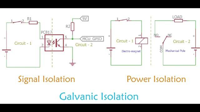
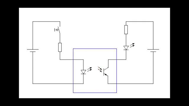
[3m:24s] The first is optical isolation.
[3m:27s] Optical isolation uses a module and a small circuit board composed of an LED and photosensitive detector,
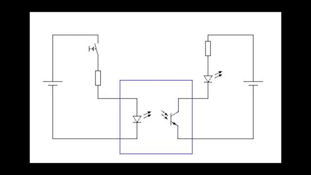
[3m:35s] with an insulating air gap, that creates the physical separation.
[3m:40s] The advantages of using optical isolation is that the size of the unit is typically quite small. They can provide higher levels of insulation than other methods because of the distance that can be created between the LED and the photo detector.
[3m:57s] A few disadvantages to using optical isolation
[4m:1s] is that these devices need to be powered separately from the signal itself.
[4m:6s] Also the signals that it can provide isolation for need to remain relatively small, so these isolators are typically ideal for low power DC signals. The other common method of isolation is transformer isolation, or sometimes referred to as electromagnetic isolation. This method of isolation uses a transformer to provide the isolation gap while still allowing the signal to be transmitted.
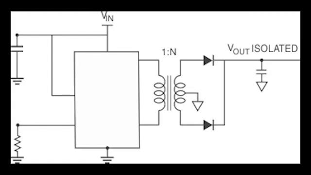
[4m:33s] This type of isolation works well with AC power signals, but because of the inefficient method of converting DC power to AC power, you will not typically see transformer isolators being used with DC power signals.
[4m:48s] An advantage to using this type of isolator is the fact that it does not require its own power source. It can simply transmit the signal passively. Both of these types of isolation techniques are used in many different form factors ranging from standalone devices to being integrated into a PLC input card.
[5m:9s] The important thing to remember is the main purpose of the isolator is to create a physical break in the galvanic connection along the signal path.
[5m:19s] This break will eliminate the distortion issues caused by ground loops.
[5m:24s] As mentioned before, this is the main use case for signal isolation. There are other situations that they may be used in which we will not cover today.
[5m:34s] However, having this basic understanding of why they are used and how they work can help you to troubleshoot issues you may encounter in your own specific work scenarios. For a full line of signal isolation hardware as well as thousands of other products, please go to our website. For more information or other educational videos, go to RSPSupply.com, the Internet's top source for industrial hardware. Also, don't forget: like and subscribe.