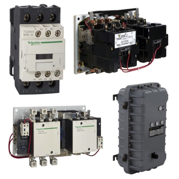
NEMA Reversing Contactors

NEMA reversing contactors are motor control devices designed to start, stop, and reverse the direction of AC motors by changing the phase sequence supplied to the motor. RSP Supply carries a full line of NEMA reversing contactors engineered for dependable performance in industrial, commercial, and specialty environments. These contactors provide full-voltage motor control and are commonly used in applications such as conveyors, hoists, pumps, machine tools, and material handling systems where bidirectional operation is required.
Reversing contactors consist of paired forward and reverse contactors that are mechanically and electrically interlocked. This interlocking design prevents both contactors from energizing simultaneously, protecting motors and control systems from short circuits or phase conflicts. While reversing contactors do not provide overload protection on their own, they are designed to work seamlessly with external overload relays, allowing system designers to select the appropriate level of motor protection for each application.
Available in a wide range of NEMA sizes, including Size 0 and larger frames, reversing contactors can be matched to specific motor horsepower, voltage, and duty cycle requirements. Multiple coil voltage options, open-frame designs for easy panel integration, and compatibility with auxiliary accessories make these contactors a flexible solution for demanding control systems. Certain models are also suitable for harsh or marine environments, offering enhanced durability where conditions require it.
FAQs
Q: What is a NEMA reversing contactor used for?
A NEMA reversing contactor is used to control the direction of an AC motor by switching the phase sequence, allowing the motor to run in both forward and reverse directions.
Q: How do reversing contactors prevent simultaneous forward and reverse operation?
They use mechanical and electrical interlocks to ensure that only one contactor, either forward or reverse, can be energized at a time.
Q: Do NEMA reversing contactors provide overload protection?
No, reversing contactors do not include overload protection. Overload relays are typically added separately to protect the motor from prolonged overcurrent conditions.
Q: What NEMA sizes are available for reversing contactors?
NEMA reversing contactors are available in a wide range of sizes, typically from Size 0 through Size 5, depending on motor requirements.
Q: What accessories are commonly used with reversing contactors?
Common accessories include overload relays, auxiliary contacts, surge suppressors, coil voltage options, and additional mechanical or electrical interlocks.
Why Buy NEMA Reversing Contactors from RSP Supply
RSP Supply offers a comprehensive selection of NEMA reversing contactors from trusted manufacturers for reliable motor direction control. Our products support a wide range of industrial applications and are designed to meet NEMA performance and safety standards. Customers rely on RSP Supply for dependable motor control components, consistent product availability, and knowledgeable support to help build reliable and compliant control systems.

