Control_Panel_Build_Series_Part_10_-_Design_PLC__IO_Schematics.pdf
In the design phase, we focus on designing the schematics for the IO portion of our control panel.
Transcript:
[0m:4s] Hi I'm Josh Bloom, welcome to another video in the RSP Supply education series. If you find that these videos are helpful to you, it certainly helps us out if you could give us a big thumbs up and subscribe to our channel.
[0m:16s] In today's video, we will move on to the next step in our panel fabrication series. If you haven't already seen the other videos in this series, we encourage you to go back and watch from the beginning so that you might better understand the entire process. The step in which we will focus on today is continuing on in the design phase of it build but focusing on the wiring schematics for the IO portion of the control panel, which includes wiring the PLC, and all terminal blocks, and other related IO hardware. Much like the power distribution schematics we completed in our last video, for completing the IO design schematics for this control panel, we will show you how we have completed this step. But please understand, there are many ways to complete this design portion of the build. Just a reminder for this portion of the design phase, it is best to utilize someone who has experience in developing and designing these types of systems such as an electrical engineer. If the system is designed incorrectly, it can be very dangerous and create hazards for anyone operating in and around the panel. So be aware of the hazards and dangerous conditions that can be associated with improper electrical design. With that knowledge in mind let's take a look at some of the things that you should consider when designing the IO schematics for your control panel.
[1m:39s] So, again, one important thing to remember when doing any kind of electrical design
[1m:44s] is to make sure that you're working with someone who has experience with this type of electrical design so that we can reduce the amount of potential hazard or danger we create
[1m:55s] in designing our industrial control panel.
[1m:58s] Again, for the purpose of our design, we are using AutoCAD and then the purpose of this video we're going to talk about examples of
[2m:5s] IO schematics. Specifically I'm going to be showing you two different examples in the panel that we actually are using. First we're going to look at our analog example and then also show you an example of some digital signals. Now, these schematics are actually from the panel that we are building and are using as an example in this series.
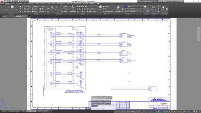
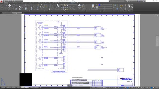
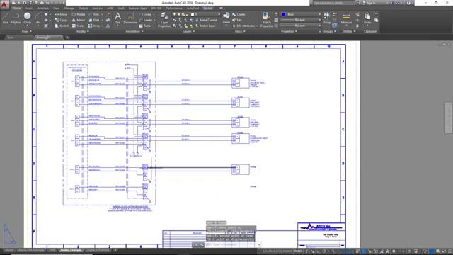
[2m:29s] So the page you see here is an example of our analog schematic. These are analog inputs. Now, let me explain a few things so that you might understand
[2m:39s] kind of what you're looking at. You'll notice here we've got several different like boxes in this drawing. Let me tell you how these are represented.
[2m:47s] This large box is representing our control panel. So everything inside this box, all of this stuff here, all these wires and all these blocks and lines are inside of our actual control cabinet.
[3m:0s] This smaller box is representing the PLC. So you can see the PLC is inside of our control cabinet, but everything inside of this box is the PLC. So all of these little blocks are little terminal points actually on the PLC, okay.
[3m:15s] Now, you can see also with inside of our control cabinet. We've got all these little blocks. These are representing terminal blocks. Okay?
[3m:23s] So we've got a whole bunch of terminal blocks. And then you can see here. These lines are representing shielding for our wires, and these lines are all wires. Okay, so we've got wires going from terminal blocks to our PLC.
[3m:36s] You can see here you've got DC three, DC negative, this is power
[3m:41s] coming from another place in our control panel that's providing power to these terminal blocks in case these instruments down here require power or loop power we refer to.
[3m:52s] The boxes out here that you see these four boxes are representing instrumentation in the field. As you can see, these boxes are not in our cabinet. This big box, they are out here. So these are field instruments. So we have wires coming from these field instruments into our control panel to these terminal blocks, and then from those terminal blocks, they go into
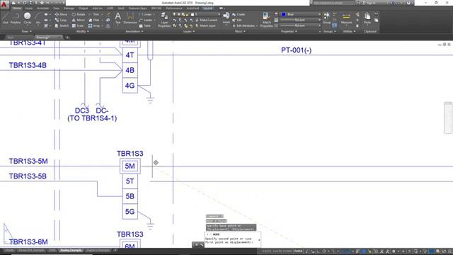
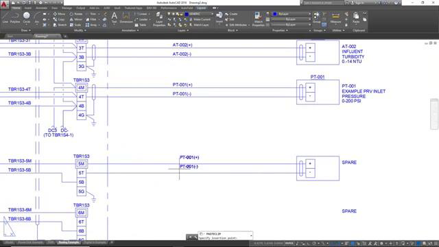
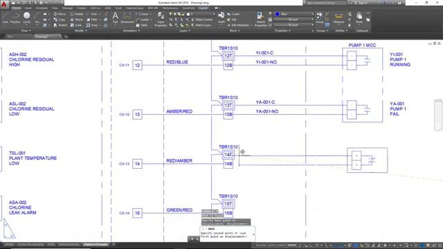
[4m:14s] our PLC. So this kind of gives you an example of how we do our layout. Now, there are a lot of different ways you can do electrical layouts and schematics just depending on the style of what you're used to, but there's a lot of different ways to represent this, but it's important that you get it correct. Again, making sure that you're working with someone who understands this. As far as drawing this goes it's very basic. We have some Pre drawn kind of instrument diagrams that we use. You can see I've got one sitting down here I'll give you an example of how we do that. We simply just copy and paste these into our drawing
[4m:49s] and then we will put them wherever wherever we need to. So if I had to add another
[4m:54s] instrument, I could simply just select this this piece here,
[4m:58s] and move it to wherever I needed to be moved to,
[5m:2s] and then add the appropriate
[5m:4s] labeling or tagging,
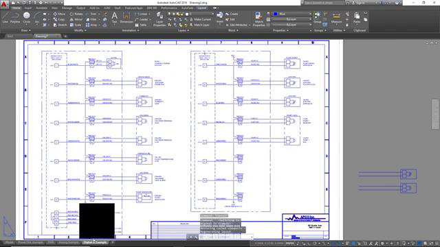
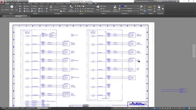
[5m:7s] and label my wires and label whatever the instrument might be here. You can see we've got some tank levels, and Turbidity, and pressures and things like that. So we can simply just label the instruments that we use for whatever we need, but this is a good example of an analog layout. Now let's move over to a digital input example. Again, this is coming exactly from the panel that we're building in this series. And you can see here we've got very similar kind of layout, but with a slightly different configuration. You can see we've got these big boxes here.
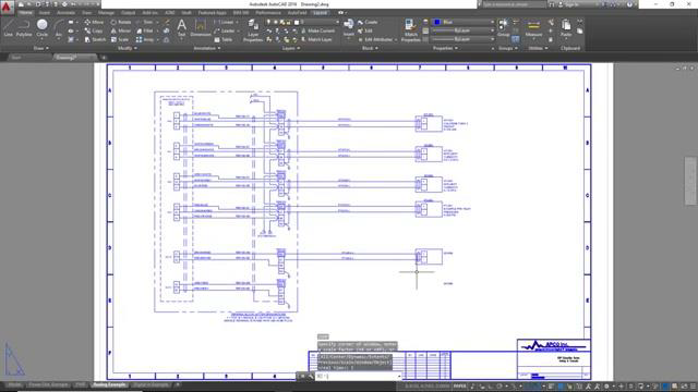
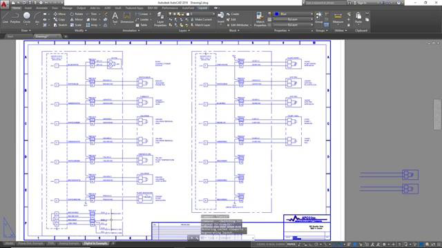
[5m:42s] Everything inside these big boxes are our panels.
[5m:45s] Again, the smaller box here and here
[5m:49s] our the PLC, so the PLC again still in our control panel.
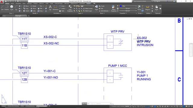
[5m:54s] Now you see here we've got sets of terminal blocks. And then outside of the panel, you can see we've got all these different devices. Now where these are digital inputs, these are just going to be more simplistic devices like switches and things like that. So you can see here we've got a little temperature switch,
[6m:9s] we've got Turbidity high switch,
[6m:13s] we've got a plant entry intrusion alarm switch. So, but these are all located outside of our panel and you can see we've got wires coming to the terminal blocks in our panel and then going into our PLC, which is again in our panel. You can see drawing this is going to be very, very similar to the way we drew our analog circuitry.
[6m:37s] We simply copy and paste some example circuits
[6m:44s] and we basically just put those wherever we need to have signals in our panels.
[6m:49s] So that could be anywhere. In this case, you can see have a normally closed contact here and that may be for, you can see here we've got a closed contact for a PRV intrusion. So just depending on your scenario, is going to be depending on what circuits that you add in your specific drawing.
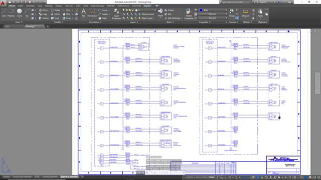
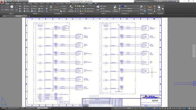
[7m:8s] But this is exactly how we do our electrical schematics and our IO and PLC schematics for our control panels. We simply go through this over and over again. Until we have all the IO that we need for our particular panel analog and digital signals. And this is the exact drawing process that we go through, and I hope this gives you a better idea of the way we do our design and schematics for the control panel that we are building.
[7m:39s] As you can see, there is a lot to consider when designing the wiring schematics for the IO portion of the control panel. This step is critical to the overall, functionality of the panel and time should be taken to make sure that nothing is missed and you get it right.
[7m:55s] As always, we appreciate your interest and participation in this series and hope you continue to join us throughout the remainder of the build process. In our next video. We will move on from the design portion of the build and look to procuring all the necessary hardware to begin fabrication. So make sure to join us next time as we continue to build.
[8m:18s] For a full line of industrial control panel hardware and thousands of other products, please go to our website. For more information or other educational videos go RSPSupply.com, the Internet's top source for industrial hardware. Also, don't forget: like and subscribe.


