Control_Panel_Build_Series_Part_8_-_Design_(Layout).pdf
Starting the design phase of the build... we focus on putting together a layout that will fit all of the hardware that is needed for the build by using our previous design that was put together during the preliminary design phase of the build process.
Transcript:
[0m:4s] Hi I'm Josh Bloom, welcome to another video in the RSP Supply education series. If you find that these videos are helpful to you, it certainly helps us out if you could give us a big thumbs up and subscribe to our channel. In today's video, we will move on to the next step in our panel fabrication series. If you haven't already seen the other videos in this series, we encourage you to go back and watch from the beginning so you might better understand the entire process. The step in which we will focus on today is moving on from the planning stages of the build to now focus on the design of our control panel. More specifically, we will focus on the actual layout of the control panel.
[0m:44s] In the planning phases, we were able to determine the majority of the hardware that we intend to use for this build. With that knowledge, along with the preliminary design that we have already completed, we are ready to design the first panel layout for our industrial control panel. So let's get to it.
[1m:2s] So the first thing that you need to consider before any design or any layout actually takes place is what type of software that you intend to use for your design process.

[1m:11s] The software that we have chosen to use is AutoCAD for many different reasons: it's a very powerful program we find that it's compatible with lots of different types of software and a lot of people are familiar with it.
[1m:23s] In most cases, it meets the needs for our different design applications. We found it very effective type of software to use for the types of design that we encounter. Again, there are many different types of design software that can be used, so you need to determine which one will best fit your needs for your specific application. Once you decided on that
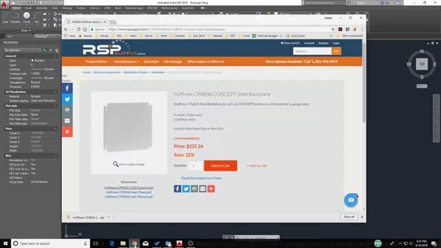
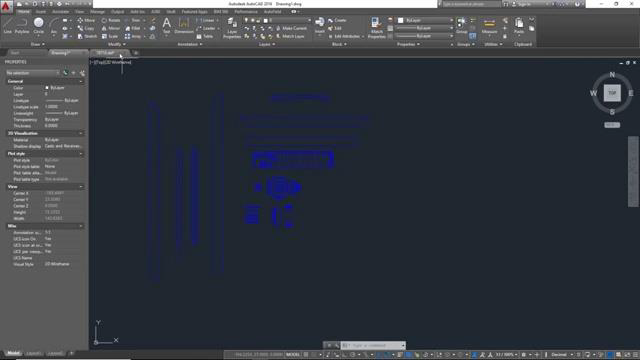
[1m:44s] design software, then you can move on to the actual design and layout process. The first thing when doing any kind of layout is actually importing or drawing the different types of individual unique pieces of hardware you'll need for your drawing. In this case, you can see we've got some examples of some wire ducting that we've actually drawn in AutoCAD, but you can also see some more complex drawings, like this PLC, that were actually imported, as well as this outlet, and a POE switch here, and a power supply, along with lots of different terminal blocks. All those are actually imported from manufacturer websites or RSPSupply.com also offers the ability to download AutoCAD drawings directly from their website. Let me show you. Here you can see that we have the back plane that's actually needed for this control panel. If I go to RSPSupply.com, I have the ability to download this right from their site to my computer and import that drawing into AutoCAD so that I don't actually have to manually draw that piece of hardware. I can simply import it. You can see here I'm copying and pasting that right into my drawing so I can better complete the layout process of this design. So, I don't actually have to draw a lot of these more complex pieces of hardware.


[2m:58s] Now that I have all the individual pieces in hardware in AutoCAD, I can start to work on the layout. One of the first thing I like to do is take the pieces of
[3m:9s] terminal block to start to group those together into these IO sections. Now, each terminal block is represented in and the PLC is one signal. So, if these are digital input terminal blocks we're using here and I have several digital inputs, so I have to group these sections of terminal blocks together to that correspond with each signal in the PLC. So, I start to group these sections together. This is one of the first things I always do.
[3m:35s] Here you can see, this is a different type of terminal block, these are terminal blocks that we use for our analog signals. But I have to do the same thing, I have to start to group these terminal block sections together
[3m:45s] because I'm going to it's going to be required that I have these large terminal block sections in my panel that correspond with each signal on the PLC.
[3m:55s] Here you can see we've got a circuit breaker that gets used to distribute AC and DC power throughout panel. We do the same thing here, we have to group the terminal, these circuit breakers together so that we know how much room it's going to take up in our panel. So that's an example of how we kind of group, those terminal block sections together.
[4m:14s] Once you've done that, then I like to actually start to go through and place my wire ducting, which you can see me doing here, in the panel. Now, I've done a lot of work in advance here, getting these pieces of wire ducting, sized and drawn correctly. Now, this is work that you'll actually have to do beforehand, but for the course of this video, I want to kind of show you how we actually do this. So, you can see me here placing wire ducting in the panels start to get an idea of the layout: where I'm going to be placing things, how things are going to be fitting. Now, this is the time also that you want to play with that layout. You can move things around at this point. We've already done a preliminary design, so you should have a good idea of where you want to place things. But this is the final design, so we want to make sure that we get it right. So, take your time in this step, make sure you get all the different pieces of hardware in your design, you don't miss anything, and then you place it where you want to.
[5m:5s] So, you can see here starting get an example of the layout that we that we're going to have in this step. You can see me here, starting to place some of these IO, excuse me, these digital terminal block sections and the analog terminal block sections in so you can start to get an idea of the spacing.
[5m:20s] Now, there's a lot of these sections that you don't see here. I'm going to take you to kind of another a little further along in the process I've done a little bit of work in advance to kind of show you a little farther along what it might look like.
[5m:31s] So here you can see I've actually gone through and grouped all the different terminal block sections I need for this particular control panel. I've already placed the PLC and I have all the power distribution hardware already at the top of the panel. So it's a little farther along, but I've done nothing different than I did in that first section.
[5m:49s] So, here I'm going to actually start taking these terminal block groups and I'm going to start placing them where I think they should go in this particular panel. Now, again, with my preliminary design, I have a pretty good idea of where I want to place these, but there always needs to be a little bit of tweaking and fine tuning in your final design process. So you can see me here placing all these analog terminal blocks. Now, here also I'm taking a little piece of wire ducting and to place it to the right of this terminal block section,
[6m:20s] and then I'm going to place a little piece of Dinrail here that's that we drew in AutoCAD,
[6m:25s] and now I'm going to add my digital terminal blocks to this drawing. Now, you can see these are already Pre grouped. But again, this is something we just did in that kind of last step to kind of show you how we do that. There's really, no difference I've just taken the time to do all of the sections before I'm starting to place it. Again, here you can see that I'm placing a little bit more wire ducting is we can kind of continue this layout process. Now again, just remember that this is the final design phase. We want to make sure that everything we do here is going to fit properly, that we have the right spacing between our
terminal blocks, that we have enough room for our wires to run through the different sections of wire ducting,
[7m:7s] but you can see we're starting to get a very complete picture of what this design is actually going to look like. At this point it's a lot of little bit of fine tuning and making sure things are a placed where we want to, but really we're pretty close here. I'm going to skip you forward to what a final design might look like here. You can see I've got all the power distribution hardware placed exactly where I want it with the right amount, I've got the PLC I've got all the IO hardware, and I've got a very complete design, including lights, enclosure. This is what you want your final design layout to look like, and at this point you're ready to move on to the next step.
[7m:44s] As you can see, there is a lot to consider when designing the layout for your control panel. This is a very important step and time should be taken to make sure that nothing is missed and you get it right.
[7m:55s] As always, we appreciate your interest and participation in this series and hope you continue to join us throughout the remainder of the build process. In our next video. We will continue on in the design phase of the control panel project focusing on the power distribution schematics portion of the design. So make sure to join us next time as we continue to build.
[8m:17s] For a full line of industrial control panel hardware and thousands of other products, please go to our website. For more information or other educational videos, go to RSPSupply.com, the Internet's top source for industrial hardware. Also, don't forget: like and subscribe.


