Panel_Build_Series_Part_3_Planning__IO_Requirements_Updated.pdf
Determining all of the different IO requirements for the control panel we intend to build.
Transcript:
[0m:4s] Hi I'm Josh Bloom, welcome to another video in the RSP Supply education series. If you find that these videos are helpful to you, it certainly helps us out if you give us a big thumbs up and subscribe to our channel.
[0m:16s] In today's video, we will move on to the next step in our panel fabrication series. If you haven't already seen the other videos in this series, we encourage you to go back and watch from the beginning of the series so that you might better understand the entire process.
[0m:31s] The step in which we will focus on today is the first part of the planning phase of the build, which is determining all of the IO requirements for the panel. This includes going over any engineering plans and looking at each piece of equipment and determining the signals that need to be either monitored or controlled on that equipment. Then we need to determine what type of signals they will actually be, for example, possibly digital inputs or analog inputs just to name a few.
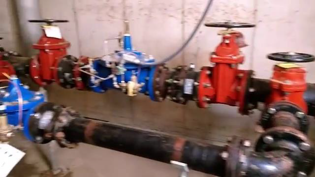
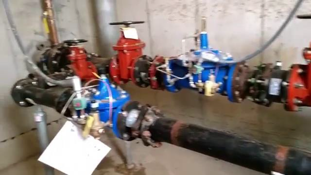
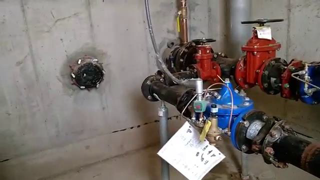
[1m:2s] At that point, once the signals have been identified, we can begin to understand some of the hardware that will be needed for this build. So, let's get started. So, one of the very first things that you should consider when trying to determine your IO is to understand that there are several different methods of trying to figure out what what type of IO you're going to need in your control panel. The most common way to determine the type of IO that you'll actually need is to be provided with engineering drawings from whoever you're providing the panel to. In the case of today's video, this is what I'll actually be showing you. I'll show you a few different examples of some different engineering drawings to help us determine the IO. Again, this is the most common method. Another very common method is to just simply match existing hardware that they may have already in place. For the case of the control panel that we’ll be building in this series, that's what we're actually doing. We go on site, we look at the existing control panel and the existing instrumentation and all of the signals and things that they want to control and monitor and we determine our IO list that way.
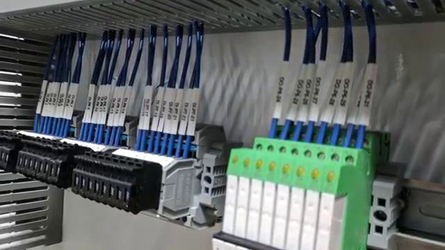
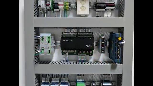
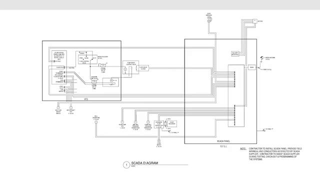
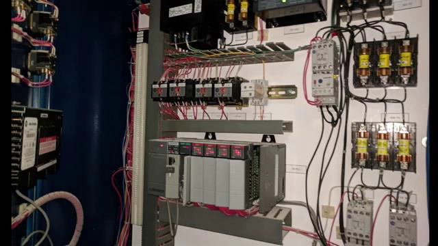
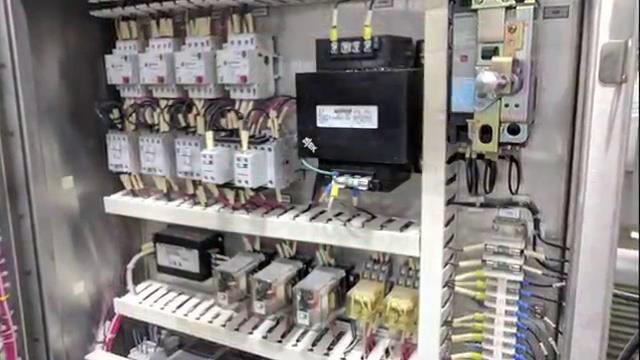
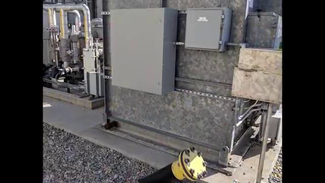
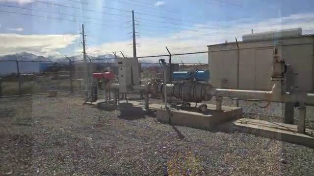
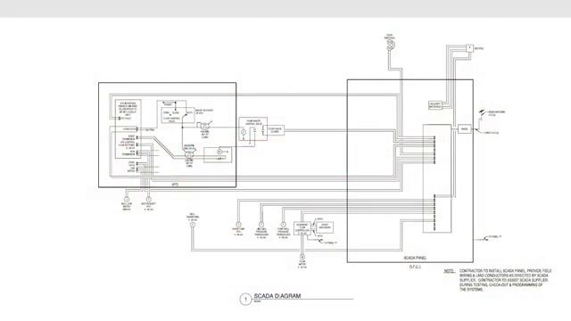
[2m:12s] Another way we can do this is by using a P&ID drawing, which is similar to an engineering drawing, but a slightly different or modified version of it. Lastly, if there's no existing hardware in place and you're not given engineering drawings, you simply go on site, determine the instrumentation that may be there and what they would like to monitor and control, and we can determine the type of IO in that fashion. So, let's first start by looking at the engineering drawings that I've talked about that we're going to be using. Again, we're going to be using two different types of engineering drawings. The first one you can see here, this is just the method that this particular engineering firm intends to use. And, the first thing we want to look at is we need to try to identify the different signals that are going to be coming into our control panel. As you can see on this drawing here, we have a SCADA panel, which is going to be our control panel, in this particular example anyway. We can see there's a lot of different signals coming in to this control panel from outside instrumentation as well as, it looks like we have a VFD here with a lot of signals that we're going to be picking up in our control panel as well. So, in this case, we're going to come through we're going to write down or mark or however we want to identify each of these signals. So here you see, we have well draw down, we have a room temperature RTD, line side pressure transducer, pump well transducer. Up here are the VFDs. So, we have a start stop. We have VFD fault, we have a local or an HOA like a run status that we're going to be picking up. We also have some door switches for like intrusion alarms they're all going to be in coming into our control cabinet, and we want to identify each of these and make sure that we don't miss anything that we need to be able to either monitor and control in the control cabinet. Now let's look at the next type of engineering drawing. This is referred to as a one line diagram. It’s providing the same information but in a very different way. You can see here, we've actually already gone through with a highlighter and kind of marked each signal that's going to be coming into our panel. In this case, each of these, all these identifying markers is a signal type. So, you can see here, we have a water level low shutdown, we have an HOA and auto, we have a running status, we have an E stop, we have a fail status, a high temperature alarm status. If you come over here, you can see we've got pressure transducers, suction water level transducers. So, a lot of different types of signals and in this case, it actually identified if it's a DI, or digital input, or an AI is an analog input. Now, a lot of drawings don't have that we need to do that work ourselves. Now, once we've gathered the different signals that we're going to be bringing into our control cabinet, that we want to put together a list, what's referred to as an IO list. Let me show you an example of that. This is just a simple Excel spreadsheet where we start to put together our IO list and you can see here, I've got some examples of some descriptions of some signals that we're going to be monitoring and what I want to do is determine what each of these signals is. Is it an analog input or output? So, in this case, we have an outdoor temperature transmitter, analog input, we have a line side pressure transducer, also an analog input. In the case of these door switches and intrusion and alarms, these are digital inputs because they're simply an on off that we're measuring. So, we're going to identify what each of these types of signals are, and this VFD start stop, it's a digital output, we're going to go through and do this to every single type of signal that we intend to monitor and control based off of the plans that we were given, or whatever we identify. Once we have all of this identified, we can then start to determine the counts in our particular IO list. You can see over here, I have an IO count. So in this case, I have three digital inputs, one digital output, five analog inputs and one analog output. This is just an example, but this is how you start to assemble your IO list and determine the IO that is required for your particular control cabinet. Once you have your count identified, at that point you can start to have a better understanding of the hardware that you will need for your control cabinet, which we will talk more about in our next video. As you can see, there is a lot that can go into determining the IO requirements of your panel.
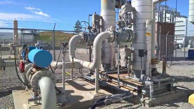
[6m:34s] It is important to take your time and get it right. In our next video, we will continue to talk more about the planning phase, but we'll focus on some hardware selection based off of the IO information we were able to find. So, make sure to join us next time as we continue to build.
[6m:53s] For a full line of industrial control panel hardware and thousands of other products, please go to our website. For more information or other educational videos, go to RSPSupply.com, the Internet's top source for industrial hardware. Also, don't forget: like and subscribe.


