
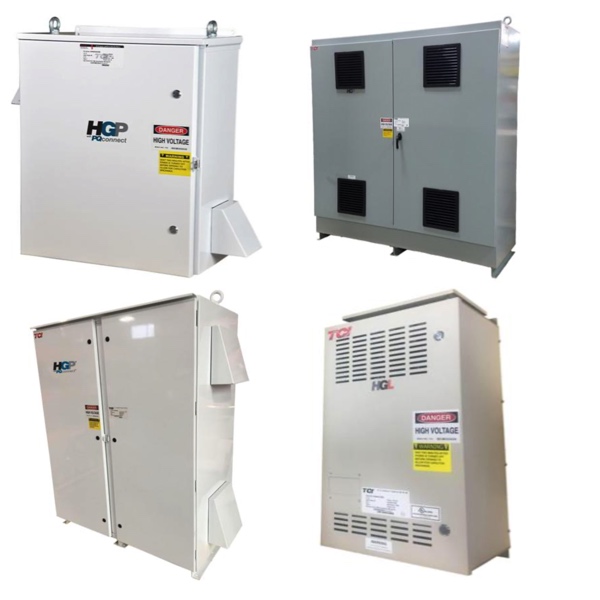
Harmonic & SineWave Filters for VFDs
Harmonic filters are critical components in electrical systems designed to reduce harmonic distortion and improve overall power quality. Harmonics are unwanted electrical frequencies generated by non-linear loads such as variable frequency drives (VFDs), rectifiers, and certain types of power supplies. If left unmanaged, these distortions can negatively affect power factor, increase system losses, and lead to overheating or premature failure of electrical equipment.
Passive harmonic filters use combinations of resistors, inductors, and capacitors to provide a low-impedance path for specific harmonic frequencies while allowing the fundamental frequency to pass through unaffected. These filters are commonly applied in power distribution systems with transformers, VFDs, and other harmonic-generating loads. By selectively tuning to problem frequencies, passive filters help protect critical components and maintain system stability.
Active harmonic filters provide a dynamic solution by monitoring electrical conditions in real time and injecting counter-currents to cancel harmonic distortion. These power electronic devices adapt to changing load conditions, synchronizing voltage and current waveforms while improving power factor toward unity. Active filters are often used in systems with varying loads where consistent harmonic mitigation is required.
FAQs
Q: How does a harmonic filter work?
A harmonic filter works by creating a low-impedance path for harmonic currents, either through passive components or by actively injecting counteracting signals. This reduces harmonic distortion, improves power quality, and stabilizes voltage and current waveforms.
Q: What is the difference between passive and active harmonic filters?
Passive filters reduce harmonics by tuning to specific frequencies using inductors, capacitors, and resistors. Active filters use power electronics to dynamically cancel harmonics by injecting compensating currents in real time.
Q: Where are harmonic filters commonly used?
Harmonic filters are commonly used in systems with non-linear loads such as VFDs, transformers, motor drives, and industrial power distribution networks.
Q: Do harmonic filters improve power factor?
Yes, harmonic filters can improve power factor by reducing harmonic distortion and aligning current and voltage waveforms more closely, though the degree of improvement depends on system conditions and filter type.
Q: Which manufacturers offer harmonic filters?
Common manufacturers of harmonic filters include Eaton, TCI, MTE, Toshiba, and Yaskawa. These manufacturers provide solutions designed to address harmonic distortion across a wide range of industrial applications.
Why Buy Harmonic Filters from RSP Supply
RSP Supply offers a wide selection of harmonic and sine wave filters designed to support reliable electrical performance in industrial and commercial applications. With solutions from established manufacturers such as Eaton, TCI, MTE, Toshiba, and Yaskawa, customers can source products that align with system requirements and industry standards. RSP Supply is a trusted source for power quality components, providing dependable products and knowledgeable support for demanding electrical environments.