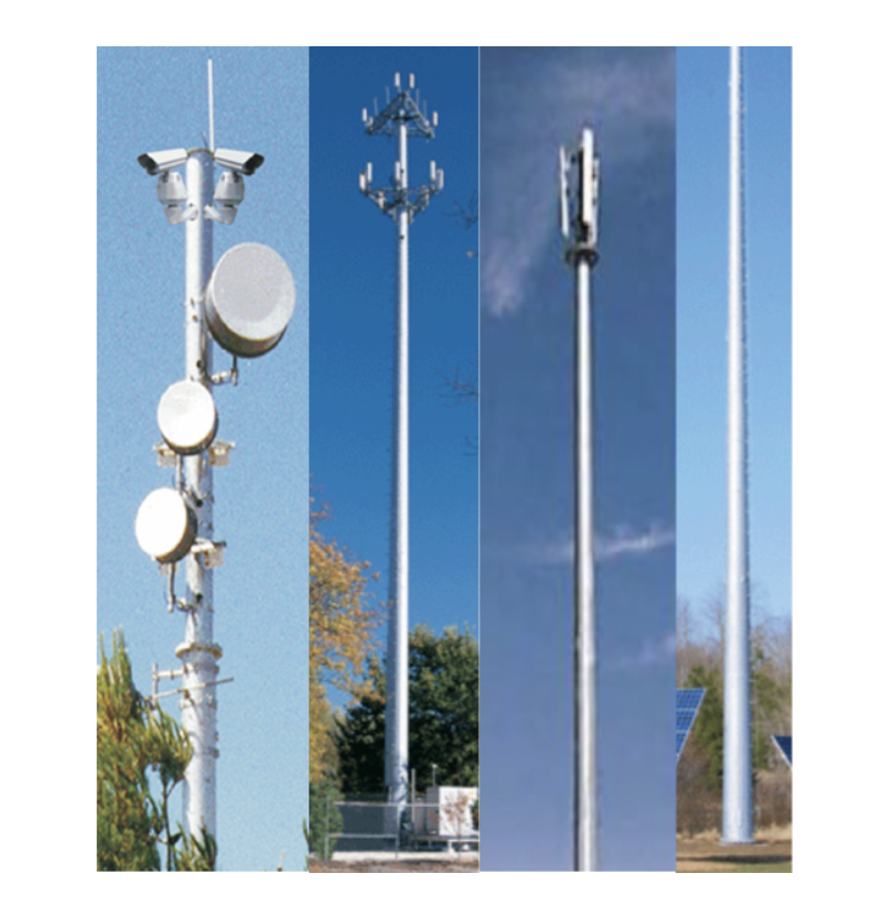
Direct Embed Poles

The telecommunication and wireless communication industries use towers, poles and mounts as support structures for antennas, personal communication systems, commercial and amateur broadcasting, home television and cellular telephones. There are two basic types of towers: self-supporting and guyed. Self-supporting towers can be three- or four-sided steel-lattice pyramids or boxes or tubular monopoles. Guyed towers are a slender, steel structure supported by one or more levels of braided and stranded high-strength steel guy cables that anchor it to the ground. When selecting the proper tower type, it is important to consider how much land it will occupy, the soil type of the land and the overall height and weight of the finished installation.
Embedded poles are self-supporting towers that can be tubular monopoles or 12-sided tapered poles. They generally range from 30 to 150 feet. Embedded poles are installed directly into the ground, which makes them ideal for areas with limited space. They are less time-consuming and more cost-effective to install. They are made of hot-dip galvanized steel to prevent corrosion in harsh outdoor environments. Embedded poles require a longer shaft for embedded installation to compensate for the length of pole buried into the ground. To determine the total pole length required, the general rule is to calculate 10 percent of the ideal fixture mounting height and add two feet. However, every structure standing above ground is subjected to lateral forces. In the case of embedded poles, it is necessary to depend on the earth to resist these forces. Sandy and loose soil conditions will not be able to support embedded pole installations.
It is important to ensure that when grounding any type of tower structure, the grounding electrode conductors be sized properly so that they can handle any potential load that the tower may encounter. If the tower is constructed of any type of metallic material, it is required by the National Electric Code (NEC) that the tower be incorporated into the grounding electrode system and be bonded to any auxiliary or supplementary grounding infrastructure. This bonding would need to occur, so that the tower’s grounding electrode conductors tie into the main sight ground or directly into Earth ground, depending on the situation.
When installing the grounding conductors for any type of tower, it is important to ensure that the conductor be run as straight as possible, avoiding any bending in the material. This can help reduce the amount of impedance in the conductor. If bending is necessary in the grounding electro conductor, a minimum bend radius of at least eight inches should always be maintained. It is also recommended that any conductors that are being used are multi stranded, individually tinned, copper conductors.
Wherever possible these grounding conductors should be installed in one continuous length in order to reduce the overall impedance of that conductor.
Splices should be avoided whenever possible. If joints or splicing are necessary, special welding techniques should be used in order to properly fuse the two different conductors together. It is always recommended that where the grounding electro conductor meets the metallic tower structure, the same special welding technique should be used. This welding technique is referred to as exothermic welding.
The best system to use for grounding a tower is to install a ground ring. A ground ring is a system of conductive grounding materials that encircle the tower. It is important that the main grounding conductor be no smaller than two gauge, bare copper wire and that this conductor is at least two and a half feet below the soil surface and have direct soil contact. Grounding rods and plates should also be used with the grounding ring and should be bonded every ten to fifteen feet, depending on the situation. A minimum of one grounding electrode conductor should be connected back to the tower itself.

